The following topology shows DvR deployment in a single data center. This deployment consists of a single DvR domain comprising a Controller layer and a Leaf node layer. The Controller layer has two controllers (for redundancy), which are deployed closer to the boundary of the DvR domain and the rest of the SPB Fabric network. The DvR Leaf nodes or Top of Rack (TOR) switches are typically access or edge switches.
All switches that belong to the DvR domain are configured with the same DvR domain ID and communicate with each other over a predefined I-SID.
The Controller nodes control the Leaf nodes and also build the gateway between the DvR domain and the rest of the Fabric infrastructure. So traffic is either routed between the Leaf nodes, or through the Controllers, to the rest of the fabric infrastructure.
Two IP subnets (Layer 2 VSNs), yellow and green, span the Leaf nodes. Each subnet is configured with a virtual IP address that is a shared among all Controller and Leaf nodes that belong to the subnet. The Controller and Leaf nodes are configured with routing interfaces to the subnets, as shown in the figure.
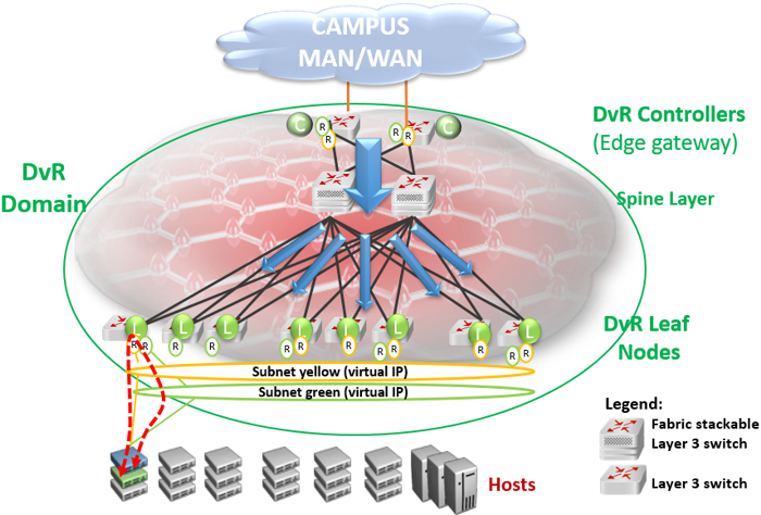
DvR works by enabling each Leaf node or Top of Rack (TOR) switch to bi-directionally route traffic for each IP subnet of which it is a member. This is done by distributing the Layer 3 configuration information (IP Unicast, IP Multicast and virtual IP configuration) needed to handle Layer 3 routing, from the Controllers to the Leaf nodes. Configuration information is pushed over the DvR Domain I-SID, as indicated by the blue arrows in the above figure.
Routing between the two IP subnets is achieved directly at the Leaf nodes when the Layer 3 distributed datapath is programmed at the Leaf Nodes, based on the Layer 3 configuration data that is pushed. Thus traffic within and between IP subnets is shortcut switched without having to traverse the central routing nodes, as shown in the figure below, if there are direct physical connections between them.

Thus, in a DvR deployment, all virtual IP and Layer 3 configuration is performed on the Controller nodes and pushed to the Leaf nodes, so that the Leaf nodes though basically Layer 2 configured switches, become fully layer 3 capable devices.